
Carbon Capture and Storage (CCS) – using geology to fight climate change
Posted in Technology on 02/02/2017 04:36 pm by Suzanna HinsonA guest blog by Mark Wilkinson (UK)
Practically everyone has an opinion on climate change by now, although for the vast majority of scientists, the weight of evidence is overwhelming – emissions of carbon dioxide and other greenhouse gases are causing climate change, sometimes referred to as global warming. One possible technology for fighting climate change is Carbon Capture and Storage (CCS) in which geology plays an important role. In fact, future generations of geologists may be employed searching for CO2 storage sites in the subsurface, rather than for the more traditional search for oil and gas.
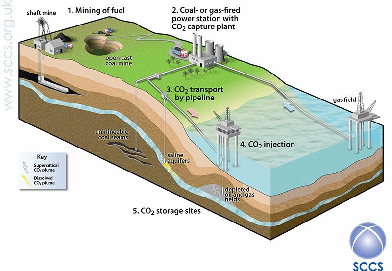
The aim of CCS is simple – to allow the continuing use of fossil fuels while reducing the emissions of greenhouse gases into the atmosphere. In the long term, the burning of fossil fuels will probably cease, but until we can rely on renewable sources of energy, we are stuck with these fuels as a cheap and reliable energy source. CO2 is emitted during many activities, including driving cars and heating homes, but the largest single sources are fossil fuel power plants, which generate electricity, followed by industries, such as steel works and cement plants. It is these that most research has been focussed on. And, in principle, the technology is simple – capture the CO2 from a source (such as a power plant; Fig. 1 below) before it gets into the atmosphere, then transport it to a suitable storage site and inject it into the ground where it will remain for tens of thousands of years.
Most power plants and industry do not emit pure CO2 – and to make best use of the underground stores, we need CO2 that is fairly pure. The technology of separating (‘capturing’) the CO2 from a gas has been the subject of much research, although some methods are well known – particularly ‘amine capture’, which has been used to produce CO2 for the fizzy drinks industry for decades. Transporting CO2 is fairly well established too – in the USA, there are thousands of kilometres of pipelines carrying CO2, mostly for use by the oil industry. There are even special ships for carrying CO2, again for use in manufacturing fizzy drinks.
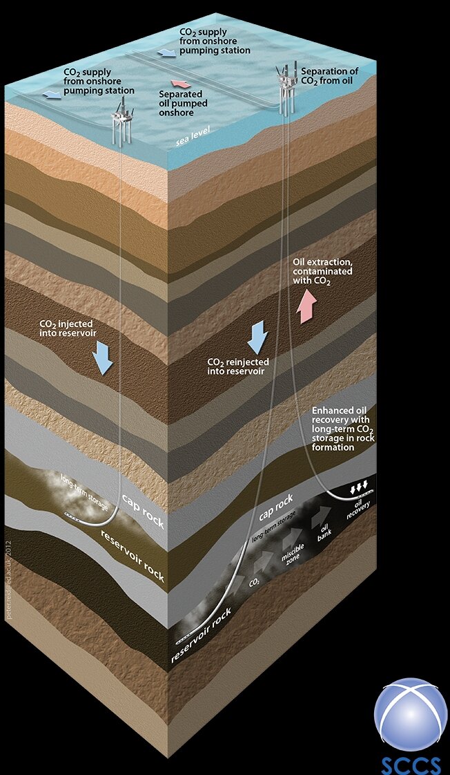 Which brings us to geological storage. The idea is simple enough – we inject CO2 into the subsurface through boreholes that are similar to the ones that the oil companies use to extract oil and gas from the subsurface (Fig. 2 left). The geological requirements for storing CO2 in the subsurface are even similar to the requirements for an oil or gas field – although, in this case, we don’t need to find any oil or gas. Since the requirements for a storage site are so similar to an oil or gas field, one idea is to use old, depleted fields. This has the advantage of giving a breath of new life to these fields, and might use existing platforms, boreholes and pipelines. In some cases, it might be possible to extract extra oil from old oil fields, in a process called enhanced oil recovery (EOR). It has been suggested that EOR may help to pay to get CCS started in places such as the North Sea. But, for really large-scale storage, we will have to go beyond the known oil and gas fields, and into suitable geological formations that have become known as ‘saline aquifers’ – a term that reminds us that fluids at typical storage depths are salty, and have no known use (if you really want salty water, there is plenty in the sea). Many of these aquifers cover tens of thousands of square kilometres in locations, such as the North Sea, and have very large potential capacities for storage.
When searching for a suitable storage location, there are three essential elements: a reservoir, a seal and a trap, and we’ll take a look at each of these in turn.
A reservoir
A reservoir is a rock that is both porous and permeable – porosity is space within the rock. We need the porosity as this is where the CO2 will be injected. Importantly, below the water table, any porosity in rocks is filled with water, or brine at depths of hundreds of meters or more. As the CO2 is injected, the water or brine that was present initially will be pushed to one side (Fig. 3 right). 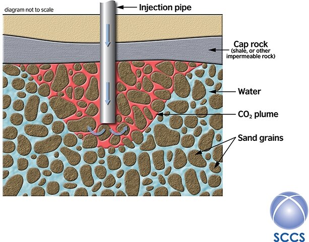
We also need the reservoir to have good permeability – the ability of fluids to flow through the porosity. Most porous and permeable rocks are sedimentary – so most storage will take place within sedimentary strata, with which fossil collectors are of course familiar. Some sedimentary rocks are better than others – well-sorted sandstones (Fig. 4 below) and some limestones are best. Silty and muddy rocks are not good, but they have other uses (see below).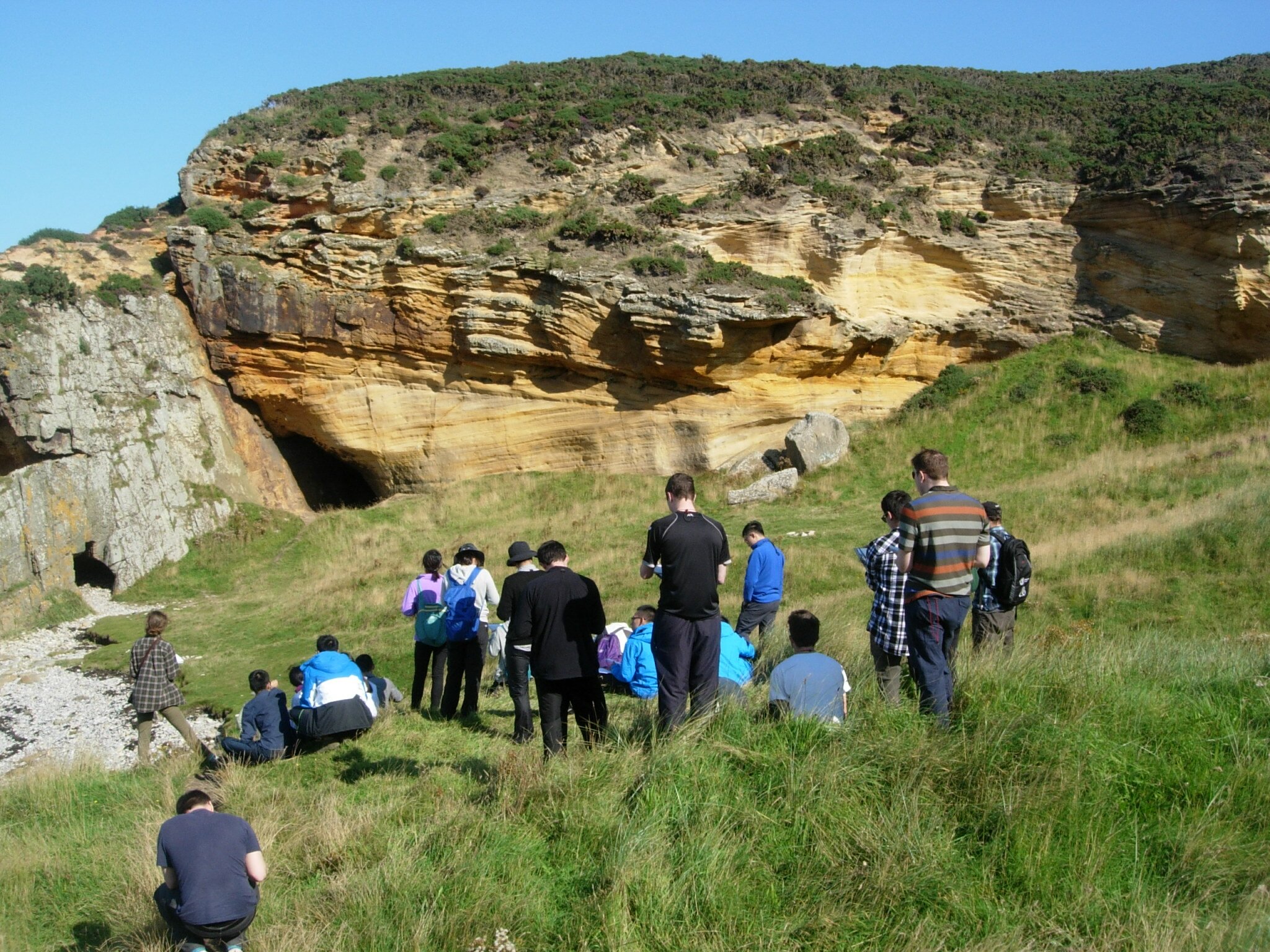
A seal
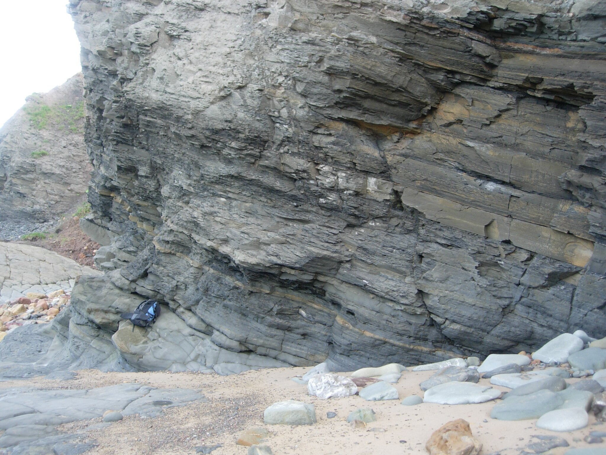
Once the CO2 is injected into a borehole, it will try to migrate upwards, driven by buoyancy (the CO2 is less dense than the water that is displaces). A rock above the reservoir is hence needed to prevent the CO2 from escaping from the reservoir and eventually reaching the surface – called a seal. These are either shales (Fig. 5 below) or evaporite rocks such as halite (rock salt).
A trap
Finally, we need a structure – this is the physical shape of the reservoir and seal. Gently folding of the reservoir and seal into a dome is the simplest, allowing the CO2 to flow buoyantly into the crest of the dome where it is securely held.
Putting it all together
Although the rocks within which we will inject CO2 are deeply buried (at least 800m depth; Fig. 2) and not available for easy study, we can see all the components of the storage system at the surface as analogues. Hence, we run field trips for students to learn what rocks in the subsurface look like. We can examine sandstones as analogues for reservoirs (Fig. 4), and study structures within them that might influence the flow of CO2 in the subsurface, such as cross bedding or interbedded shales. We can look at shale and mudstone sequences as analogues for seals (Fig. 5), looking for interbedded sandstones that might make pathways for leakage if they were connected in some way. And we can see structures (traps), although the ones we see in the field are usually much smaller than the typical subsurface structures that are normally kilometres across.
Once the CO2 is injected, we can check on its position by using seismic surveying, a technique that gives a 2D or even a 3D image of the subsurface. The technique was developed by the oil industry and is identical in principle to the ultrasound imaging used in hospitals to scan unborn babies. However, seismic surveys are expensive, so a lot of research is going on into cheaper methods.
So what is the role of the geologist in all this? Identifying a potential storage site is only the beginning – the real challenge is lack of data to really understand what the rocks are like in the subsurface, and hence how the CO2 will behave once injected. A borehole drilled in the North Sea to typical storage depths costs £10 million or more (so there are never many of them) and only gives direct information about the rock through which it is drilled, that is, only about a column of rock a few centimetres in width. Yet a storage site might be 10km across and that’s a lot of subsurface with no data. So we need to extrapolate our very limited data away from the borehole(s), to answer questions such as: Does the reservoir rock occur all the way across the potential storage site, or perhaps it becomes thinner in one or more directions? Does the reservoir change its character as we go away from the borehole, for example, change porosity or permeability? Does the seal rock cover the entire site or are there gaps that the CO2 might escape through? Fortunately, there is plenty of experience of dealing with these problems, as the oil industry faces exactly the same challenges with oil and gas fields. The basic tools are conceptual models of how we understand that sediments relate to one another in 3D (called facies models), which have been constructed by studying well-exposed examples of similar ancient rocks or by studying equivalent modern environments. Any text book on sedimentology is full of such models, usually presented as 3D diagrams.
An important first task then is to work out in what environment the sediments of a reservoir were deposited. Typical examples might be a sandy desert or a shallow tidal sea. Fortunately, these have all been well studied by both academics and the oil industry. Knowledge of the overall setting of the area is also essential, for example, if the reservoir was deposited by a river, which way was it flowing? Rivers flow from high ground to low ground (usually the sea), so if we have worked out the geography at the time of deposition (the paleo-geography), then we have valuable constraints as to how the sediments might be arranged spatially, for example, which way sand-rich river channels might be oriented. One use of our geological understanding is in building a computer model of CO2 injection. This is now a standard technique, using software that was initially designed for the oil industry to model oil and gas flow in reservoirs. It enables us to answer questions, such as: How will the pressure change in the reservoir during and after injection? And how far will the CO2 flow away from the borehole?
So what are the downsides to CCS? As the CO2 is injected into the reservoir, it pushes the water or brine that was initially present to one side (Fig. 3). This causes an increase in the pressure in the reservoir, which must be carefully managed to prevent earthquakes – small ones in an offshore setting are perhaps tolerable as they will not be felt onshore, but for onshore storage, these need to be strenuously avoided. And CCS costs money – at present it is almost always cheaper to emit CO2 into the atmosphere rather than capture and bury it. However, in the long term, it has been worked out that it will be cheaper to prevent climate change than to cope with the effects. There is also the question of unexpected leakage – and, although this is understandably a concern for the general public, most experts think that this is very unlikely to occur. However, it is worth remembering that a leak in a maritime setting could cause local acidification of the ocean, although globally the effect would be much less than continued unabated emission of CO2.
There are no current plans for CCS in the UK, after the UK Government cancelled a long-running competition for funding in 2015. However, there are places in the world where CCS is alive and kicking, including in: Canada (the Boundary Dam power plant and the Quest tar-sands upgrader); Norway (the Sleipner gas field); and Australia (the Gorgon gas field). And large volumes of CO2 are injected into the subsurface in the USA for enhanced oil recovery, having been transported long distances across the North American continent. So all the technology needed for CCS is proven – it works – but the costs are at present too high. The future of CCS depends ultimately on how much we value the environment, balanced against our desire for cheap fuel to power our energy-intensive lifestyles.
About the author
Mark Wilkinson is Senior Lecturer in Geological Carbon Storage at the University of Edinburgh, UK, where he runs a Masters (MSc) in Carbon Capture and Storage, as well as teaching geology to students.
Further Reading
Returning carbon to nature: coal, carbon capture, and storage, by Mike Stevenson, Elsevier, Paperback ISBN: 9780124076716.
This article will also appear in the popular geology magazine Deposits (https://depositsmag.com/).
Figure captions
Fig. 1. (1) An overview of carbon capture and storage, from obtaining fossil fuels including coal by mining. (2) The fuel is used to make electricity in a power plant; (3) then transported (in this case by pipeline) and (4) injected into (5) underground storage. Note that the CO2 will normally be injected to depths of at least 800m below the ground or seabed. Fig. 2 gives a better idea of typical storage depths. (Image courtesy of Scottish Carbon Capture and Storage (SCCS), www.sccs.org.uk.)
Fig. 2. The injection of CO2 into storage in an offshore setting. Note the depth of injection compared to a typical oil platform which is about 100m high. The figure shows both storage in a ‘saline aquifer’ (left) and injection for enhanced oil recovery into an oilfield (right). (Image courtesy of Scottish Carbon Capture and Storage (SCCS), www.sccs.org.uk.)
Fig. 3. As the CO2 (red) is injected into the reservoir, it pushes aside the water (blue) and is contained below the caprock (grey). (Image courtesy of Scottish Carbon Capture and Storage (SCCS), www.sccs.org.uk.)
Fig. 4. Well-sorted sandstones are the best reservoirs, and sands deposited as dunes in sandy deserts are among the best of these. Here, students from the University of Edinburgh sketch Permian desert sandstones exposed at Clashach Cove on the shores of the Moray Firth in Scotland. This is a well-known locality, due to the well-exposed fault visible on the left side of the cave.
Fig. 5. Shales are the typical seal rocks that, in the deep subsurface, will prevent the CO2 from escaping from the reservoir and eventually reaching the surface – here seen superbly exposed at Berwick on the English/Scottish border. Rucksack for scale.